


The Elgar AT8000 is a versatile programmable DC power system designed for automated test equipment (ATE) applications, offering a high-density, modular platform that can accommodate both power supply and electronic load modules within a single mainframe. This system is engineered for use in production test environments, incoming inspection, repair facilities, and quality control, where it can provide power stimulus or simulate real-world load conditions.
### System Architecture and Modularity
The AT8000 system is built around a 5.25-inch high mainframe, available in master and slave configurations. A single master chassis can house up to six independent channels, which can be a mix of DC power supply modules and electronic load modules. By paralleling power modules, a single chassis can deliver up to 1200W. The system is expandable to a total of 16 channels across multiple chassis, allowing for configurations up to 19.2 kW.
* **Master Chassis:** Acts as the controller, housing the GPIB interface and programmer. It can manage up to 16 channels, distributed across one or more slave chassis.
* **Slave Chassis:** Expands the system’s channel count and capabilities. These units require connection to a master chassis for programming and control.
* **Module Types:**
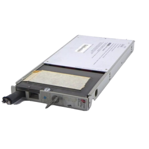
* **DC Power Supply Modules:** Linear design for fast response time and low ripple. Available in various voltage and current ratings. Example module configurations include 32 Vdc at 6.25A.
* **Electronic Load Modules:** 300W modules capable of simulating real-world load characteristics for testing, evaluation, and burn-in of DC power supplies and other components. These modules operate in four primary modes: constant current, constant voltage, constant resistance, and transient operation. Individual load modules can be paralleled for up to 1800W per chassis.
### Electrical Specifications
While specific module specifications vary, the system supports a range of voltage and current outputs configurable via its modular design.
* **Output Voltage Ranges:** Configurable based on installed DC power modules. Example: modules with 7 VDC, 10 VDC, 20 VDC, 32 VDC, 40 VDC, 80 VDC, 160 VDC, 320 VDC are referenced.
* **Output Current Ranges:** Dependent on the installed modules. For example, a 32V module may support up to 6.25A.
* **Maximum Power per Chassis:** Up to 1200W with paralleled power modules.
* **Total System Power:** Expandable up to 19.2 kW in multi-chassis configurations.
* **Ripple and Noise (Voltage Mode):**
* 1.5 millivolt RMS or 0.01% of rated output voltage (whichever is greater) from 20 Hz to 100 kHz for single chassis.
* Master-slave configurations: 5 millivolts RMS or 0.01% of rated output voltage (whichever is greater) from 20 Hz to 100 kHz.
* 15 millivolts peak-to-peak or 0.05% of rated output voltage (whichever is greater) from 20 Hz to 200 MHz.
* Master-slave configurations: 15 millivolts peak-to-peak or 0.1% of rated output voltage (whichever is greater) from 20 Hz to 20 MHz (typical).
* **Efficiency:** 50% to 60% at full rated output power and nominal AC input voltage, dependent on module voltage.
* **Protection Features:** Standard overcurrent sensing and overvoltage protection with SCR crowbar shutdown. Load isolation (confidence) relays are also standard. Polarity switching relays are optional.
### Interfaces and Programming
The AT8000 system is designed for integration into automated test environments.
* **Remote Programming:** Primarily through IEEE-488 GPIB interface. The system can be controlled remotely with one selectable bus address.
* **Programming Languages:**
* **ABLE (Atlas Based Language Extension):** For simple, easy-to-use mnemonics for programming.
* **CIIL (Control Interface Intermediate Language):** Conforms to U.S. Air Force MATE guidelines, available for AT8000A.
* **Local Control:** Front-panel keyboard and display for direct programming and operation. The keyboard features multi-level functionality with increment/decrement keys.
* **Readback Capability:** With the built-in test option, voltage and current readings can be monitored for DC power modules, Auxiliary Drive Modules (ADMs), and electronic DC loads.
* **Remote Sense Terminals:** Included for increased flexibility and accuracy.
### Physical Characteristics
* **Form Factor:** 19-inch wide rackmount chassis.
* **Chassis Height:** 5.25 inches.
* **Depth:** 21 inches.
* **Weight:** Approximately 80 lbs (36 kg) for a chassis with six power modules.
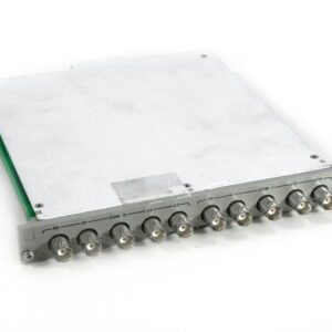
* **Output Connections:** Standard terminal strip or optional individual MS connectors per power module.
* **Input Power Connection:** Standard three-wire, 20A plug; optional three-wire MS type connector.
### Compatibility
* **Master/Expansion Configurations:** Supports master and expansion chassis for scalability up to 16 channels.
* **Module Compatibility:** Designed to accept both DC power supply modules and electronic load modules within the same chassis.
* **ATE Integration:** Compatible with MATE applications through CIIL programming.
### Why Choose Aumictech for ELGAR AT8000?
At Aumictech, we specialize in sourcing and supporting high-performance ATE equipment. Whether you require robust programmable DC power systems for complex testing scenarios, reliable electronic load modules for accurate simulation, or integrated multi-channel solutions for consolidated bench space, our team ensures the ELGAR AT8000 delivers maximum performance and flexibility for your engineering and procurement needs.


Reviews
There are no reviews yet.