


The Elgar SW1750A is a high-performance AC power source engineered for demanding ATE (Automated Test Equipment) and power line disturbance simulation applications. It offers versatile waveform creation capabilities, allowing for the simulation of complex real-world power occurrences such as sags, surges, spikes, and distorted waveforms. The unit is designed to meet stringent waveform requirements, including significant DC content, low distortion, and minimal noise and ripple, making it suitable for compliance testing against various EMC and avionics standards. Its modular design allows for scalability, with the SW Series expandable from 1.75 kVA up to 22.2 kVA, and offers full rated power output up to an ambient temperature of 45°C.
### Technical Specifications
**Power Output:**
* **Model:** SW1750A
* **Apparent Power:** 1750 VA maximum, per phase
* **Expandability:** The SW Series is expandable from 1.75 kVA to 22.2 kVA through master/slave configurations.
* **Output Configuration:** Capable of single-phase or three-phase output configurations, with some models allowing switching via menu selection and wiring changes.
**Electrical Specifications:**
* **Input Voltage (USA):** Supports 208V 3-Phase input. Also supports 187 to 264 VRMS L-L for 3-Phase operation (3-Wire USA).
* **Output Voltage (Phase to Neutral):**
* 0 to 156 VRMS L-N (Range 0)
* 0 to 312 VRMS L-N (Range 1)
* **Output Voltage (Phase to Phase Calculation):** 0V to 700V
* **Output Current Per Phase:**
* 13A at 135V in 156V range (1750 VA maximum)
* 6.5A at 270V in 312V range (1750 VA maximum)
* Higher currents achievable in multi-kVA systems.
* **Output Current (Parallel Mode):**
* 0A to 22.5A (312V range)
* 0A to 45A (156V range)
* **Frequency Range:** DC or 2 Hz to 6 kHz standard output frequencies. Specifications typically apply to DC, 40 Hz to 5 kHz. For output frequencies greater than 1 kHz, the maximum slew rate is 1 kHz per second.
* **DC Content:** Up to 312V DC content is supported without derating of output power.
* **Low Distortion:** Total Harmonic Distortion (THD) of 0.25% to 100 Hz.
* **Crest Factor:** Up to 4.0 (peak output current to RMS output current).
* **Power Factor:** 0.6 (standard), 0.35 for Intl. Rectifier; 0.99 with PFC option.
* **Line Regulation:** ±0.025% of full scale for a ±10% input line change (DC, or 40 Hz to 5 kHz).
* **Load Regulation:** ±0.025% of full scale voltage for a full resistive load to no load. Above 1 kHz, add ±0.015%/kHz.
* **Amplitude Stability:** ±0.1% of full scale over 24 hours at constant line, load, and temperature, with remote sense.
* **Voltage Accuracy:** ±0.1% of range. Above 1 kHz, add 0.2%/kHz. Add ±0.1% of full scale for “AC PLUS DC” mode.
**Waveform Capabilities:**
* **Arbitrary Waveform Generators:** Three separate arbitrary waveform generators for independent, complex waveform creation on all three phases simultaneously.
* **Waveshape Library:**
* 50 built-in waveshapes (e.g., sine, square, triangle, clipped sine, sine with spikes, fractional dropouts, sine with DC offset, ±DC with ripple, Fourier square waves, Taylor series waves, sine wave with noise).
* Ability to create and store an additional 50 user-designed waveshapes.
* **Sequence Programming:**
* Complex sequence or event programming using time or cycle-based transient segments.
* Sequence library comprises 1000 segments.
* Up to 100 segments and 32 different waveshapes can be used in a single sequence.
* **Waveform Simulation:** Capable of creating fractional or multi-cycle dropouts, spikes, surges, sags, and distorted waveforms from the front panel.
* **Measurement Capabilities:** 4½ Digit Analog to Digital Measurement System.
* Phase to Neutral RMS Voltage
* Phase to Phase RMS Voltage (calculated)
* RMS Current
**Interfaces:**
* **GPIB:** Includes GPIB (IEEE 488.2) for remote control and automation. Connector pinout is detailed in the operation manual.
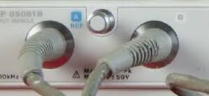
* **External Input (EXT in):** BNC connector for external signal input. Connector pinout is detailed in the operation manual.
* **Direct Fault Indicator (DFI):** Connector for fault signaling. Connector pinout is detailed in the operation manual.
* **Slave Connector:** For master/slave configurations. Connector pinout is detailed in the operation manual.
* **BNC Outputs:** For scope viewing of waveforms.
**Physical and Environmental:**
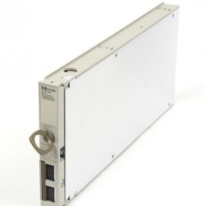
* **Dimensions:** 8-3/4 inches high for the SW 5250A model, suggesting a compact form factor for its power output.
* **Weight:** 127 pounds.
* **Operating Temperature Range:** 0°C to 45°C (32°F to 113°F). Delivers full rated power up to 45°C.
* **Storage Temperature:** Not specified in available documentation.
* **Humidity:** Not specified in available documentation.
* **Altitude:** Not specified in available documentation.
**Compatibility and Standards:**
* **ATE and Power Line Disturbance Simulation:** Designed for ATE and power line disturbance simulation testing.
* **Compliance Testing:** Meets waveform requirements for compliance testing to many EMC and avionics standards. Specific standards include Airbus DO-160 and Boeing standards.
* **MIL-STD-704 Transients:** Factory-supplied sequencing program available.
**Other Features:**
* **Front Panel Controls:** Offers front panel programming and control.
* **Graphic LCD Display:** Features a graphic LCD display.
* **Sequence Library:** 1000 segments, 100 segments per sequence, 32 waveshapes per sequence.
* **AC and/or DC Output:** Can function as a true DC power supply, with high DC content waveforms supported.
* **Self-Test:** System self-test functionality.
* **SCPI Command Control:** Supports SCPI (Standard Commands for Programmable Instruments) for direct command control.
Why Choose Aumictech for the Elgar SW1750A?
At Aumictech, we specialize in supplying high-performance AC power sources. Whether you need precise simulation of AC line conditions, reliable power for critical testing, or robust waveform generation for complex ATE applications, our team ensures the Elgar SW1750A delivers maximum performance for your application.


Reviews
There are no reviews yet.