


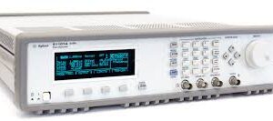
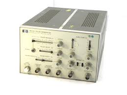
The HP/Agilent 8005B is a 20 MHz dual-output pulse generator engineered for digital circuit testing, time-domain analysis, and general electronic characterization. It delivers simultaneous positive and negative pulse outputs plus a separate TTL output, all independently controllable. With pulse widths spanning 25 ns to 3 s, transition times as fast as 10 ns, and amplitude control from 300 mV to 10 V, the instrument accommodates both precision pulse generation and rapid signal switching across a wide operational bandwidth.
## Technical Specifications
• **Output Frequency:** DC to 20 MHz external trigger; 0.15 Hz to 10 MHz square wave; double pulse mode to 10 MHz
• **Pulse Width:** < 25 ns to 3 s with jitter < 0.1% of setting + 50 ps
• **Rise/Fall Time:** ≤ 10 ns to 2 s; non-linearity 30 ns)
• **Pulse Amplitude:** 300 mV to 10 V with 3-step attenuator and continuous vernier adjustment
• **Output Impedance:** 50 ohms ± 10% or high impedance selectable
• **Pulse Delay:** < 100 ns to 3 s with jitter 80% (0.3 Hz to 1 MHz); > 50% (1 MHz to 20 MHz)
• **TTL Output:** +4.6 V, 50 ohm impedance, normal or complement mode
• **Trigger Output:** > +2 V across 50 ohms, width > 6 ns; input-to-output delay ≈ 35 ns
• **External Trigger Input:** DC to 20 MHz, ±10 V maximum, 1 kΩ impedance; sensitivity: 2 Vpp sine or ±1 V peak pulses
• **Preshot/Overshoot/Ringing:** < 5% of pulse amplitude
• **Power:** 115/230 V rms (+10%, −15%); 48–440 Hz
• **Operating Temperature:** 0°C to 55°C
• **Dimensions:** 130 mm H × 426 mm W × 290 mm D
• **Weight:** 7 kg
## Key Features
• Simultaneous positive and negative pulse outputs with independent control
• TTL-compatible output (all parameters variable except amplitude)
• Synchronous and asynchronous gating modes
• Programmable pulse delay and width with tight jitter specifications
• External trigger input supporting DC to 20 MHz signals
• Selectable 50 ohm or high impedance output
## Typical Applications
• Digital logic circuit testing and validation
• Time-domain waveform characterization
• Pulse train generation for circuit stimulation
• TTL/CMOS signal simulation
• Gate control in synchronous measurement systems
## Compatibility & Integration
External triggering accepts standard logic and analog signals. Gate input impedance is 1 kΩ, DC coupled, with gate amplitude range 2 V to 20 V (negative polarity). Maximum external voltage protection: ±10 V.


Reviews
There are no reviews yet.