


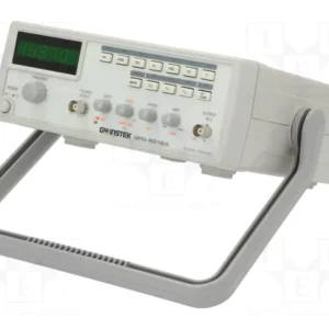
The Instek GFG-8215A is a 3 MHz function generator delivering precision signal generation across seven distinct frequency ranges from 0.3 Hz to 3 MHz. It generates sine, triangle, square, and ramp waveforms with dedicated TTL and CMOS outputs, making it suitable for bench testing, circuit development, and educational laboratory work. The instrument provides greater than 10 Vpp output into 50Ω loads with adjustable DC offset spanning -5 V to +5 V, dual-stage 20 dB attenuation, and variable attenuation control. Duty cycle adjustment operates from 20% to 80% with signal inversion capability up to 1 MHz, while external voltage control of frequency (VCF) accepts 0 V to 10 V input at a 100:1 ratio. This model distinguishes itself by omitting built-in display and frequency counter functions.
## Technical Specifications
**Signal Generation**
• Waveforms: Sine, Triangle, Square, Ramp, TTL, CMOS
• Frequency range: 0.3 Hz to 3 MHz (7 ranges)
• Output amplitude: >10 Vpp into 50Ω
• Output impedance: 50Ω ±10%
• DC offset: -5 V to +5 V (into 50Ω)
• Attenuator: Two-step (20 dB × 2) plus variable
• Duty cycle: 20% to 80% adjustable, up to 1 MHz maximum
• Waveform flatness: <0.3 dB (0.3 Hz–300 kHz), <0.5 dB (300 kHz–3 MHz)
• Sine distortion: <2% (0.3 Hz–100 kHz), <5% (100 kHz–3 MHz)
• Square wave distortion: <5% (0.3 Hz–100 kHz)
• Triangle distortion: <2% (0.3 Hz–100 kHz)
• Square wave rise/fall time: ≤25 ns
• Pulse wave rise/fall time: ≤100 ns
**External Control**
• VCF input: 0 V to 10 V ±1 V (100:1 modulation ratio)
• VCF input impedance: 10 kΩ ±10%
**Physical & Environmental**
• Power: AC 115 V/230 V ±15%, 50/60 Hz
• Dimensions: 251 mm W × 91 mm H × 291 mm D
• Weight: 2.0–2.4 kg
• Operating temperature: 0°C to 40°C
• Storage temperature: -10°C to 70°C
• Operating humidity: 80% maximum (non-condensing)
## Key Features
• Seven overlapping frequency bands eliminate dead zones
• Dual output channels: main signal (50Ω) and TTL/CMOS secondary
• Variable attenuator plus fixed 20 dB stages for precise amplitude control
• Signal inversion on duty cycle-modulated outputs
• Low output impedance (50Ω) for direct instrument coupling
## Typical Applications
• Circuit verification and troubleshooting across audio to RF frequencies
• Educational demonstrations of waveform theory and modulation
• Component testing requiring variable-frequency stimulus
• Equipment calibration using precision waveform references
## Compatibility & Integration
The 50Ω output impedance enables direct connection to standard test equipment and RF instruments without additional impedance matching. VCF input accommodates external modulation sources for frequency sweep and dynamic control applications. TTL/CMOS outputs interface directly with logic analyzers and digital circuits.


Reviews
There are no reviews yet.