

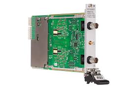
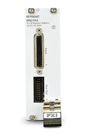
The NI PXI-6542 is a high-performance digital waveform generator and analyzer module for PXI systems. It delivers 32 independently configurable channels, each usable as input or output, alongside four programmable function interface (PFI) channels with per-channel direction control. Operating at a maximum clock rate of 100 MHz with a maximum data channel toggle rate of 50 MHz, the module interfaces with TTL voltage standards: 5 V, 3.3 V, 2.5 V, and 1.8 V logic levels. Channel-to-channel skew remains ±600 ps typical, ensuring tight timing correlation across parallel data paths.
– Technical Specifications
Channels & Architecture
• 32 data channels with per-channel direction control
• 4 PFI channels with per-channel direction control
• Maximum clock rate: 100 MHz
• Maximum data channel toggle rate: 50 MHz
• Channel-to-channel skew: ±600 ps (typical)
Memory & Storage
• Onboard memory options: 1 MBit, 8 MBit, or 64 MBit per channel
• Memory type: SDRAM
• Synchronization and Memory Core (SMC) technology enables flexible allocation of script instructions, waveforms, and sample storage
Timing & Synchronization
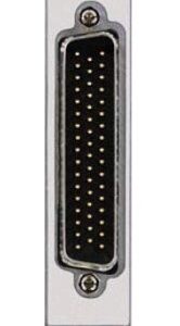
• Clock sources: internal VCXO with divider, external clock input (SMB), PXI_STAR backplane, and STROBE (DDC connector)
• Onboard clock frequency range: 48 Hz to 100 MHz (200 MHz/n, where 2 ≤ n ≤ 4,194,304)
• External clock input frequency range: 20 kHz to 100 MHz
• Delay adjustment resolution: 10 ps
• Generation data delay: 0.0 to 1.0 sample clock periods (for ≥25 MHz)
• Generation data delay resolution: 1/256 of sample clock period
• Sample clock offset: software-selectable 0.0 ns or 2.5 ns
• Sample clock modes: rising or falling edge
Voltage Levels
• 1.8 V logic: low 0 V typical (max 0.1 V), high 1.7 V typical (min 1.8 V)
• 2.5 V, 3.3 V, and 5 V logic supported
– Key Features
• Flexible per-channel I/O configuration optimizes mixed-signal test scenarios
• SMC technology maximizes memory utilization across competing waveform and instruction needs
• Sub-nanosecond delay adjustment (10 ps resolution) supports precise timing control
• Typical DDC connector latency of 15 ns enables predictable synchronization
– Typical Applications
• Digital circuit functional and parametric testing
• Digital communication system characterization
• Automotive electronics validation
• Aerospace and defense system verification
– Compatibility & Integration
The PXI-6542 integrates into PXI chassis, leveraging the PXI_STAR synchronization backplane. Clock and data signals export via SMB connectors and DDC connectors for multi-module coordination.


Reviews
There are no reviews yet.